_画板-1-1.png.webp)
Introduction
A ribbon blender is a commonly used equipment for mixing powders and granules, known for its uniform mixing and high efficiency. This article will introduce the working principle, structural components, and related calculations of the ribbon blender to better understand its operation mechanism.

More details please reference our website
Working Principle
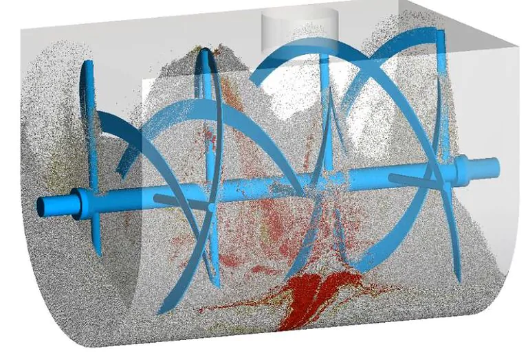
The ribbon blender mixes materials through the rotation of double helical ribbons. The inner and outer helical ribbons rotate in opposite directions, creating a complex circulation movement within the mixing chamber, achieving uniform mixing.
Structural Components
The ribbon blender primarily consists of the following parts:
- Machine Body (1): The supporting structure of the entire equipment.
- Mixing Chamber (2): The space for holding and mixing materials.
- Agitator (3): The core component, consisting of inner and outer helical ribbons.
- Feed Inlet (4): The channel through which materials enter the blender.
- Discharge Outlet (5): The channel through which mixed materials are discharged.
- Engine (6): The power source.
- Reducer (7): Adjusts the speed of the agitator.
- Feed Screw Conveyor (8): Transports materials to the mixing chamber.
- Discharge Screw Conveyor (9): Transports mixed materials out of the blender.
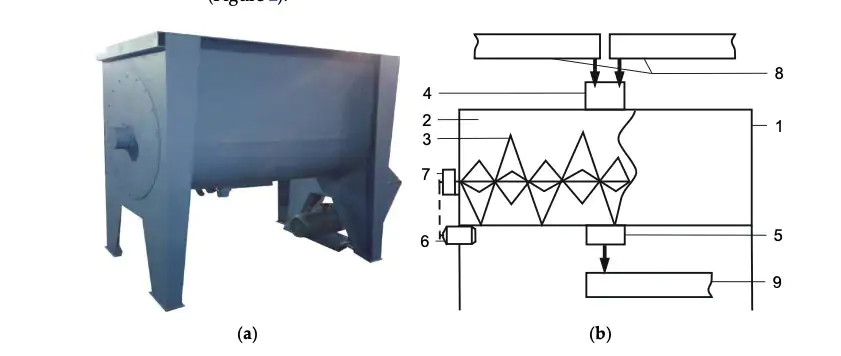
Structural diagram of the mixer
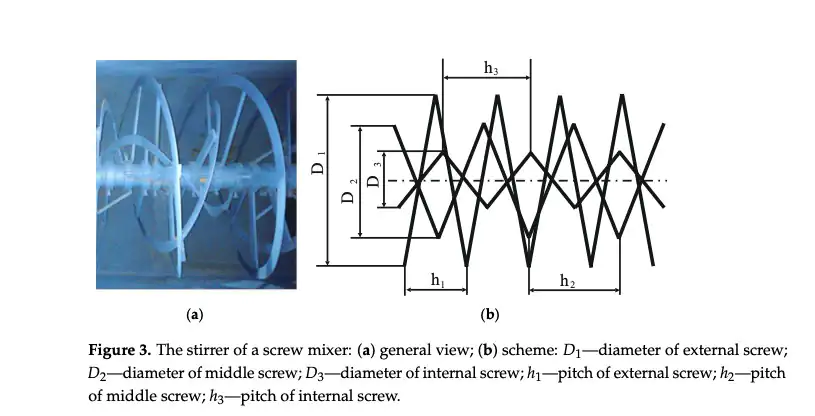
Agitator Structure
The agitator is the key component of the ribbon blender. As shown in Figure 3, the agitator consists of three layers of helical ribbons, with varying diameters and pitches.
The geometrical parameters of the agitator are shown in the table below:
| Parameter | Symbol | Value | Unit |
|---|---|---|---|
| Outer ribbon diameter | D1 | 1 | m |
| Middle ribbon diameter | D2 | 0.75 | m |
| Inner ribbon diameter | D3 | 0.4 | m |
| Outer ribbon inner edge diameter | d1 | 0.9 | m |
| Middle ribbon inner edge diameter | d2 | 0.65 | m |
| Inner ribbon inner edge diameter | d3 | 0.26 | m |
| Outer ribbon pitch | h1 | 0.3 | m |
| Middle ribbon pitch | h2 | 0.4 | m |
| Inner ribbon pitch | h3 | 0.24 | m |
| Ribbon width | g | 0.05 | m |
| Agitator length | l | 1.8 | m |
Theoretical Analysis Assumptions
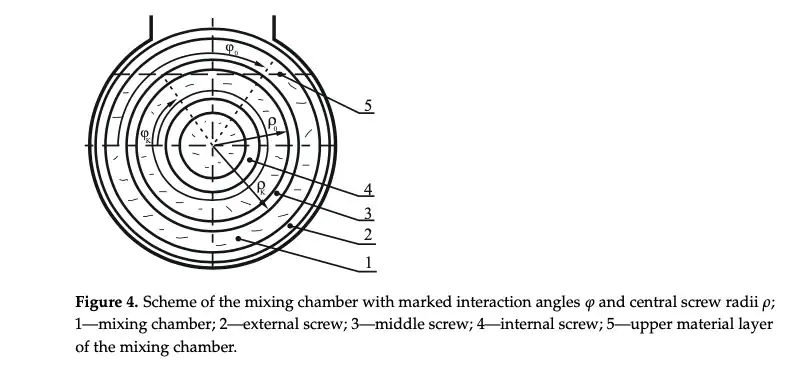
The theoretical calculations use mechanical analysis methods. Figure 4 shows the layout of the mixing chamber, including the initial angle (ϕ0) and final angle (ϕK) of the agitator with the material, and the initial radius (ρ0) and final radius (ρK) of the agitator. The assumed parameters of the agitator are shown in Table 1, with an angular velocity range of 1.05–4.19 rad/s.Figure 4: Layout of the mixing chamber
Experimental Verification
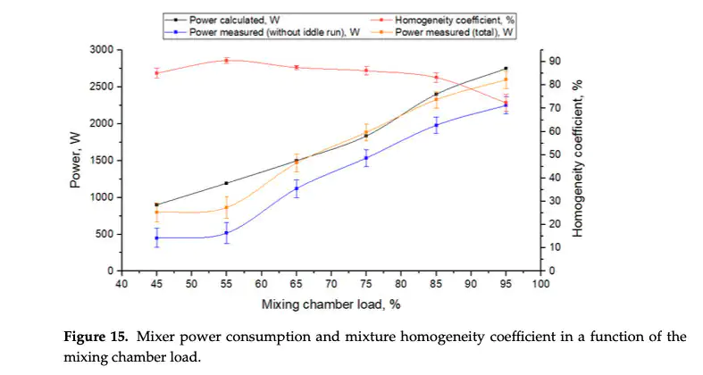
To verify the power consumption model, experiments were conducted mixing rye and barley, using peas as a control material. Figure 15 shows the results of the power consumption test, including the no-load power (blue curve), total power input (orange curve), and the mixture homogeneity coefficient (red curve) as a function of the mixing chamber load.
Conclusion
From the structural analysis and experimental verification of the ribbon blender, the following conclusions can be drawn:
- The design parameters of the agitator significantly impact mixing efficiency and power consumption.
- Properly adjusting the speed of the agitator and the geometrical parameters of the helical ribbons can improve mixing uniformity and reduce energy consumption.
The theoretical models and experimental data provided in this article offer important references for the design and optimization of ribbon blenders.


_画板-1-副本-3-pxeey2xejyohpkvf07tglhvew6ks2ts3pjvhagm60c.png.webp "NICETY MACHINERY Co., LTD")